INSIGHTS
Single-Shaft Combined Cycle Units Averaging 99.7% Reliability
This article was originally published on Gas Turbine World.
Introduced more than 50 years ago, gas turbine combined cycle power plants represent a significant advancement in the world of power generation, blending efficiency, economy, versatility, and environmental responsibility.
Design Configurations
As the concept evolved over time, mostly through advances in gas turbine technology, such plants have become highly popular. They are commonly available in two design configurations: single-shaft, with gas turbine, steam turbine, and generator on the same shaft; and multi-shaft, with each gas turbine generator (one or more) and a single steam turbine generator on separate shafts.
Historically, single-shaft units have been more common in 50Hz regions and multi-shaft more prominent on 60 Hz grids. Although local reasons do not favor one over the other, there are clear preferences in some areas like Japan where building space is scarce and at a premium.
Mitsubishi Power's Contributions
Since the early 1980s, Mitsubishi Power has successively executed both single- and multi-shaft combined cycle projects for both 50 and 60 Hz power generation. The following factors usually tip the scale in favor of single-shaft (SS) units:
-
Plant Footprint
- Typically, single-shaft units require one-third less land area than an equivalent MW multi-shaft plant.
-
Part-load Efficiency
- Running fewer single-shaft units is typically more efficient than shutting down one or more gas turbines in a multi-shaft plant.
-
Reliability
- Over the last 5 years, 14 monitored units in 50 and 60 Hz regions around the world have averaged over 99.7% reliability.
- Part-load operating flexibility and cost considerations are also growing more important. Mainly because combined cycle plants on large power grids fed by intermittent renewable energy sources are increasingly filling the role of dispatchable assets.
Part-load Considerations
It is generally accepted that low-load operation of large combined cycle installations designed around two or more single-shaft units is more efficient than a multi-shaft plant of comparable gas turbine technology.
Take for example, a plant powered by three single-shafts units. When called upon to operate at less than 2/3 of full load output, one or two of the single shaft units can be shut down to optimize part load plant efficiency.
When one or more gas turbines in a multi-shaft arrangement are shut down to satisfy a part-load dispatch situation, steam flow and operating conditions deviate from the optimum design values, and steam cycle efficiency will be negatively impacted.
Although both single-shaft and multi-shaft plants are typically designed for highest efficiency at full load output, partial load operation of a multi-shaft plant results in a steeper fall-off in performance at low loads. This is due to lower efficiency of remaining gas turbines operating at part load, and to the off-optimum performance of the steam turbine set.
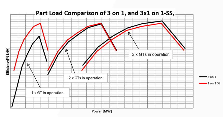
Fig. 1. Part-load efficiency of a 3-on-1 multi-shaft plant compared to three single-shaft units. The fall-off in efficiencies beyond peak values is attributed to negative effect HRSG duct firing has on combined cycle efficiency.
Part-load Efficiencies
At low loads only one of the three single-shaft units operates. Whereas the multi-shaft unit has only one gas turbine running with its steam turbine at 1/3 load, far off design flow, and hence at relatively low efficiency.
Result is that multi-shaft plant efficiency is considerably less than an SS plant over a wide range of low load demand.
At moderate load (center set of curves), with two SS plants operating and two GTs running in the multi-shaft plant, the curves show a similar characteristic. But SS plant efficiency (red curve) is slightly higher than the multi-shaft plant (black curve).
This reflects only a slight efficiency advantage of two smaller steam turbines versus a large steam turbine over this part load spectrum.
At higher loads, all three SS units operate and all three gas turbines in the multi-shaft unit operate. Here, the multi-shaft plant (black curve) has the efficiency advantage since its large steam turbine set is typically more efficient when operating closer to its design point than the 3 smaller ones of the SS units.
Note: In each case, the efficiency curves are shown to climb, peak, and then fall off with increasing load. This drop-off is attributed to the negative impact on combined cycle efficiency of supplemental HRSG duct firing to increase steam turbine power output beyond its unfired output condition. Despite this negative impact on efficiency, some plant owners who operate in areas where the spot MWh price can change considerably, elect the relatively low-cost design option ($/kW) to take advantage of high market value of incremental power during times of peak load on the power grid.
Plant Design Factors
Electric power generation equipment design and operational requirements are often driven by regional or site-specific limitations and topography.
Japan, for instance, is a small country, roughly 70% mountainous, with a surface area similar to California. This raises the value (and cost) of flat land which makes footprint optimization of power generation infrastructure a priority.
The high cost of imported fuels such as liquefied natural gas (LNG) is also an important factor which puts a premium on high efficiency power generation, to minimize fuel consumption. Also on the ability to handle difficult, low-cost waste fuels like blast furnace and coke oven off-gases.
Those factors all favor single-shaft units over multi-shaft plants, despite their more complex design. Added engineering scope includes more detailed analysis of rotor dynamics, vibration, and alignment of compound shafting incorporating three, or more, heavy rotating elements, differential thermal expansion along a long single rotor shaft, and individual casings.
Single-shaft Fleet
Since the 1980s, Mitsubishi Power has designed and installed over 150 single-shaft combined cycle power plant units around the world.
Several of them burn difficult to handle low-heating value fuels such as steel mill byproduct gas and syngas (primarily CO+H2) produced by IGCC plant gasification of coal and other low-grade feedstock.
For example, a steel mill unit in Kimitsu, Japan features a 165 ft. long single-shaft train that incorporates an 87MW axial fuel-gas compressor – in addition to in-line gas turbine, generator and steam turbine.
The gas turbine fuel gas is a blend of byproduct blast furnace gas transported through a 3.5 meter diameter pipeline (forefront of the photo) mixed with coke oven gas carried in smaller pipeline.
This low-calorific-value gas mixture (1,050 Kcal/Nm3 vs. ~ 9,000 Kcal/ Nm3 for natural gas) is pressurized by the axial compressor which is connected to an F class (1,350 ⁰C) gas turbine through a gearbox at the end of the steam turbine.
The net 300MW power train, which began commercial operation in 2004, has since logged over 130,000 actual operating hours.
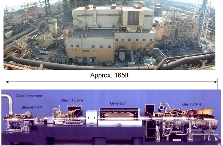
Fig.2. Steel mill in Japan. This 50 Hz 300MW M701F single-shaft combined cycle unit incorporates an 87MW low-Btu fuel gas compressor connected via a gearbox at the end of the steam turbine shaft.
Integrated Gasification Plant
Another Mitsubishi Power single-shaft unit, commissioned in 2003 for a 430 MW IGCC plant in Negishi Refinery, is powered by a M701F combined cycle fueled by syngas (5.9 MJ/Nm3) produced on-site through a Texaco vacuum residue gasification process.
These two examples incorporated F-class gas turbines, considered state-of-the-art at the time of construction, despite operating with difficult to handle gases such as BFG+COG and vacuum residue syngas.
Earlier single-shaft plants in Japan were powered by D-class gas turbines operating on low-cost fuels. Similar low-calorific-value fuel projects featuring Mitsubishi single-shaft units were installed starting in the late 1990’s in the Netherlands, China, Korea, Ukraine and Hungary.
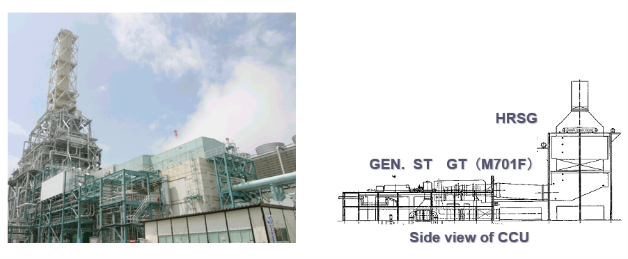
Fig. 3. M701F single-shaft unit. Combined cycle plant powered by an M701F gas turbine fueled by syngas was commissioned in 2003.
Two Different Layouts
The Mitsubishi Power fleet of 150 single-shaft units contains two power train arrangements. The original configuration, a Combustion turbine-Steam turbine-Generator (CSG) arrangement, featured a rigid coupling between the gas turbine and steam turbine – resulting in a power train that had to be started and stopped as a single unit.
That design has been superseded by a more flexible Combustion turbine-Generator-Steam turbine (CGS) configuration with an SSS self-synchronizing clutch inserted between the generator and steam turbine. This improvement allows the steam turbine to start up separately (or remain idle on turning gear) while the gas turbine is already producing power.
In some instances, older multi-shaft combined cycle units have been replaced by the latest in single-shaft technology, incorporating a more highly rated and more efficient gas turbine.
In 2020, for example, the existing 60 Hz JAC-class multi-shaft plant at the original MHI Takasago long-term validation facility was replaced by a nearby new plant called T-Point 2 featuring an enhanced M501JAC single-shaft unit nominally rated at 566MW at 64% efficiency.
This upgraded validation facility provides operators invaluable reassurance that state-of-the-art single-shaft units are being sold and installed – with high confidence – by confirming their design performance and reliability.
Additional recent single-shaft combined cycle projects incorporating 60 Hz M501J and JAC gas turbines include plants in the United States, Mexico, and Brazil. Several 50 Hz applications in Thailand powered by M701J and JAC gas turbines include two 2,640MW projects in Thailand, each containing 4 x 660MW single-shaft blocks.

Fig. 4. J-POWER USA project in the U.S. 1200MW gas-fired plant powered by two M501JAC single-shaft combined cycle units.
Third-party Reliability Data
In 2008, Mitsubishi Power signed a contract with Strategic Power Systems (SPS), an independent consulting company which gathers operational and maintenance data directly from worldwide power generation companies to confirm the reliability and availability statistics of participating power stations (aka, ORAP database).
Reliability of single shaft units is affected by the design complexity of longer shaft power train configurations, and the rotor dynamics involved in plant design. Full alignment between gas turbine and steam turbine design teams is fundamental.
To avoid unexpected vibration issues, special attention must be given to the stiffness and damping characteristics of the bearing supports, bearing span design, rotor flexibility of interconnected shafts, and differential casing-to-rotor thermal expansion during start-up.
The fact that Mitsubishi’s single-shaft fleet of 14 monitored units has averaged over 99.7% reliability is an outstanding achievement – considering the complex design arrangements associated with this type of combined cycle power station.
Learn more about our gas turbines here.
In this whitepaper, we examine how just a 1% increase in gas turbine reliability can increase profitability and minimize risk.


