M701G Series
-
Standalone Gas Turbine Output
330 MW class
-
Combined Cycle Output
500 MW class / 1,000 MW class
-
Combined Cycle Efficiency
More than 59%
High-performance large-capacity gas turbines for 50Hz power generation
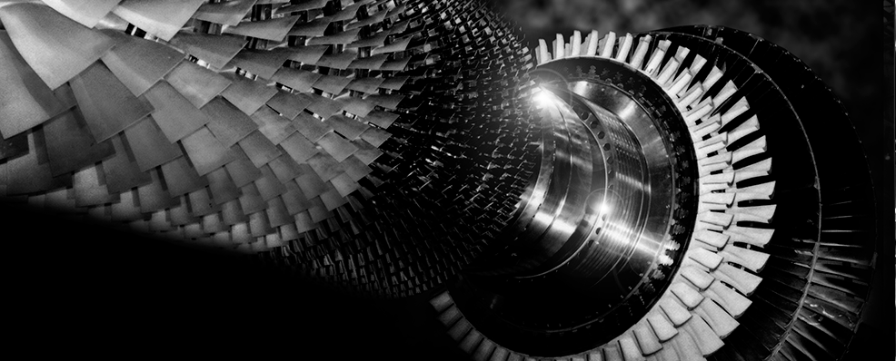
In February 1997, the first unit of the 1,500°C Class M501G Series gas turbines came into commercial operation. This series features the use of steam for cooling combustors. Developed as a model with a similar design, the M701G Series for 50 Hz power generation began commercial operation at the middle of 1999.
Overall Design
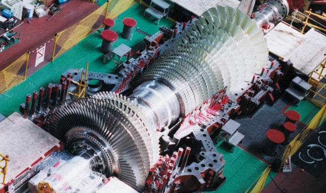
The gas turbine unit is based on the basic structure adopted in the early 1970s that has accumulated a track record of at least 40 years. Its main features are as follows:
- A compressor shaft end drive reduces the effect of thermal expansion on alignment
- A rotor with simple single-shaft two-bearing support
- A rotor structure has bolt-connected discs with the torque pins in the compressor section and CURVIC couplings in the turbine section to ensure stable torque transmission
- An axial flow exhaust structure advantageous in combined cycle plant layouts
- Horizontally split casings that facilitate field removal of the blades with the rotor in place
Compressor
Axial flow compressors designed with advanced airfoil design technologies are introduced. They feature large capacity, high efficiency and a high pressure ratio. Variable inlet guide vanes ensure operational stability at the start-up and enhanced performance at partial load in combined cycle operation.
The inlet guide vanes and variable stationary vanes at the first three stages are controlled to ensure stable operation at the start-up and enhanced performance at partial load in combined cycle operation.
Combustor
A premixing low NOx combustor is a steam-cooled type, composed of one pilot burner and eight main burners that surround it. The combustor has an air bypass mechanism that enables fuel-air ratio regulation in the combustion region.
Turbine
Four-stage axial flow turbines in a three-dimensional aerodynamic design are adopted. The vanes at the first three stages are air-cooled. Among these, those at the first two stages adopt directionally solidified (DS) materials with thermal barrier coating (TBC). Despite the rise in temperature, application of advanced cooling technologies and the TBC helps to maintain the metal temperature of turbine blades at the level of conventional gas turbines.
Configuration
| M701G | ||
|---|---|---|
| Compressor | Number of Stages | 14 |
| Combustor | Number of Cans | 20 |
| Cooling Method | Steam Cooled | |
| Turbine | Number of Stages | 4 |
| Rotor | Number of Rotors | 1 |
| Output Shaft | Cold End | |
| Rated Speed | 3,000 rpm | |
| Gas Turbine | Approx. L × W × H | 14.4 × 6.2 × 6.7 m |
| Approx. Weight | 490 ton | |
Simple Cycle Performance
| M701G | ||
|---|---|---|
| Frequency | 50 Hz | |
| ISO Base Rating | 334 MW | |
| Efficiency | 39.5 %LHV | |
| LHV Heat Rate | 9,110 kJ/kWh | |
| 8,630 Btu/kWh | ||
| Exhaust Flow | 755 kg/s | |
| 1,664 lb/s | ||
| Exhaust Temperature | 587 °C | |
| 1,089 °F | ||
| Exhaust Emission | NOx | 25 ppm@15%O2 |
| CO | 10 ppm@15%O2 | |
| Turn Down Load | 60 % | |
| Ramp Rate | 22 MW/min | |
| Starting Time | 30 minutes | |
Combined Cycle Performance
| M701G | ||
|---|---|---|
| 1 on 1 | Plant Output | 498.0 MW |
| Plant Efficiency | 59.3 % | |
| 2 on 1 | Plant Output | 999.4 MW |
| Plant Efficiency | 59.5 % | |
| Starting Time | ‐ | |
Performance Correction Curves
-
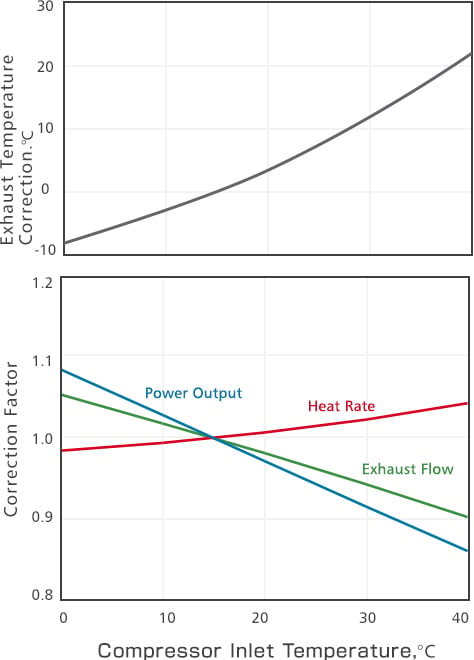
Effects of Compressor Inlet Temperature on Gas Turbine Performance (Typical)
-
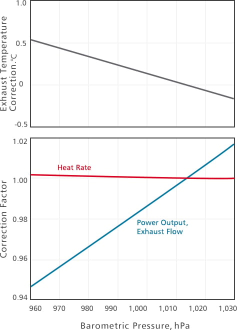
Effects of Barometric Pressure on Gas Turbine Performance (Typical)
Typical Plant Layout - 1 on 1 configuration, single-shaft
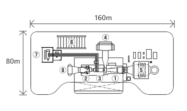
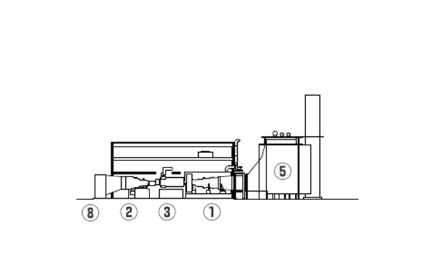
- Gas Turbines
- Steam Turbines
- Generators
- Inlet Air Filter
- Heat Recovery Steam Generator (HRSG)
- Electrical / Control Package
- Main Transformer
- Condenser
Typical Plant Layout - 2 on 1 configuration
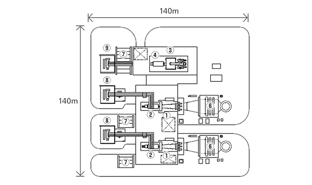
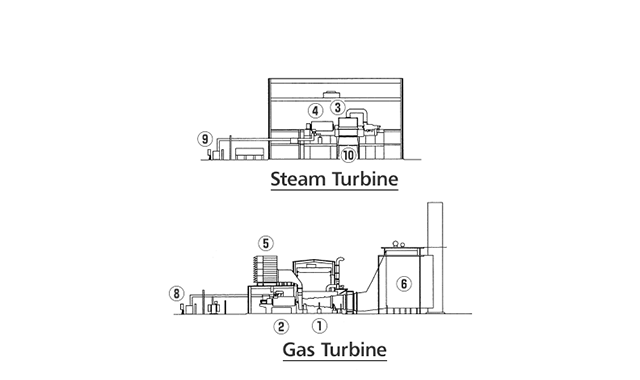
- Gas Turbines
- GT Generator
- Steam Turbines
- ST Generator
- Inlet Air Filter
- Heat Recovery Steam Generator (HRSG)
- Electrical / Control Package
- GT Main Transformer
- ST Main Transformer
- Condenser
Main Delivery Records
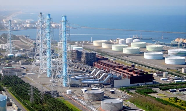
Higashi-Niigata Thermal Power Station Unit 4, Tohoku Electric Power Co., Inc. (Japan)
1,700 MW, 4 x M701G
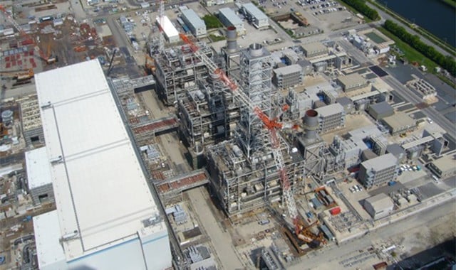
Chiba Thermal Power Station Unit 3, TEPCO Fuel & Power, Inc. (Japan)
1,500 MW, 3 x M701GAC
Products
- GTCC
- Steam Power
- IGCC
- Geothermal
-
Gas Turbines
- Product Lineup
- Comparative Performance
-
Technical Information
- Gas Turbines for Mechanical Drive Applications
- Cutting-Edge Elemental Technology Producing 1600°C Class J Gas Turbines
- Development of High-Efficiency Gas Turbine Applying 1600°C Class J Technology
- Combustor Technologies Supporting Stable Operation
- Overview and Verification Status of T-Point 2 Demonstration Facility
- Comprehensive Efforts from Development to Manufacturing
- Summary of Orders
- Development History
- Product Selection Assistant (Middle & small Class)
- Aero-derivative Gas Turbines
- Steam Turbines
- Boilers
- Air Quality Control Systems (AQCS)
- Generators
-
Control Systems
- What is DIASYS?
- DIASYS Netmation
-
DIASYS Optional Products
- IR-S Infrared Flame Detector
- Net IR-S Infrared Flame Detector
- Rail Mounting Net IR-S
- Boiler Tube Leak Detector
- Shaft Vibration Analyzer
- Simulator
- Advanced Combustion Pressure Fluctuation Monitoring System (A-CPFM) / Combustion Pressure Fluctuation Monitoring System (CPFM)
- Multi-Coal Fired Boiler Optimum Control
- FXtoLS Adapter
- Fuel Cells
- Others
- Catalogue
- HIACS Series
- Technical Report