IR-S Infrared Flame Detector
Overview
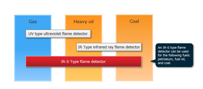
IR-S type infrared flame detector is an excellent high-sensitivity type superior in "reliability of detection", "maintainability" and "economy".
It can support diversification of boiler fuel and low NOx (nitrogen oxide) operation. By detecting "average value" and "variation" of infrared intensity of burner flame light which is transmitted through a light guide (optical fiber) to an infrared sensor (semiconductor element), the detector can distinguish the flame and the infrared rays due to the red heat of the furnace wall and detect the flame fluctuation in the burner ignition zone.
The IR-S type infrared flame detector has low-brightness flame detection sensitivity and a wide dynamic range, so that it can be applied to various fuels such as gas, heavy oil, and coal.
Features
High Sensitivity Design
High sensitivity to the intensity of flame enables stable detection of the burner flame. The flame is detected through the unlit zone.
Extended Detection Range
The sensor has 100 times dynamic range of a conventional product and allows stable detection from slow combustion to a high intensity flame. No sensitivity adjustment is required for the sensor at the site.
Easy Maintenance
A spherical lens is used to eliminate the need to clean the sensor window during boiler normal operation.
Long-life Sensor
Because a long-life infrared semiconductor sensor element is used, periodic replacement is not necessary.
Fewer Number of Panels
The detector unit is compact with a space-saving design which allows one panel to cover 40 corners.
System Configuration
Flame Detector Panel

Flame Detector Panel

Flame Detector Unit
Flame Detector Main Unit


Flame Detector Main Unit
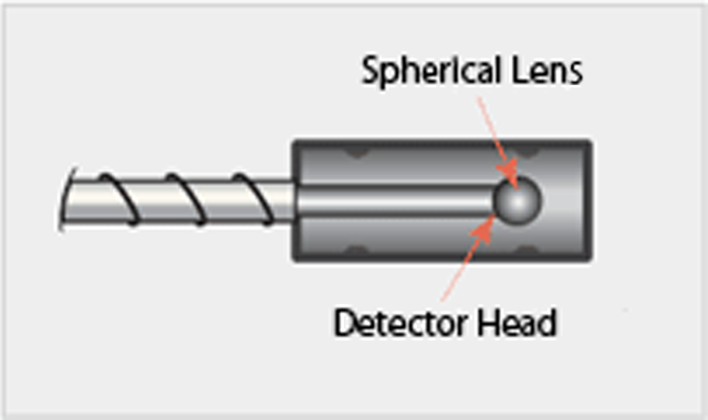
Cross Sectional View of Sensor Head
For Fuel Oil Burner
The following example applies to a fuel oil burner.

Specifications
Sensor Unit
The specifications of the sensor unit are as follows.
| Environmental protection | Explosion-proof (Exd II BT4), waterproof | |
|---|---|---|
| Dimensions | Entire Length | As required |
| Guide Pipe | 50A (40A) | |
| Detection Wavelength | 500 - 1,100nm | |
| Allowable Temperature | Detector Head Component | Not exceeding 200℃ |
|---|---|---|
| Cooling Air | Temperature | Not exceeding 60℃ |
| Air Pressure | In-furnace pressure +1.5kPa or greater | |
| Air Flow | At least 1.0Nm3/min per sensor (fan capacity should be designed at 1.5Nm3/min per sensor to account for when withdrawn inspection takes place) |
Flame Detector Panel
The specifications of the flame detector panel are as follows.
| Type | Closed indoor self-standing type, with access hatches on front and back | |
|---|---|---|
| Dimensions | 2,300mm (H) ×810mm (W) ×800mm (D) | |
| Configuration |
|
|
| Output Signals | Flame on | 1a |
| Low luminance level | 1a | |
| Power loss | 1b | |
| Contact capacity | AC/DC 48V, 1.25A | |
| Ambient Temperature | 0 to 50℃ | |
Retrofit/Upgrade
Retrofit or upgrade with a new type of flame detector system will not requires boiler side modifications. Many of existing facilities and parts will be reused.
| Equipment Name | Existing Methods of Flame Detection | |
|---|---|---|
| UV Type | IR Type | |
| Sensor Unit | Replaced | Replaced |
| Flame Detector Panel | Replaced | Replaced |
| Sensor Cable | Reused | Replaced |
| Guide Pipe | Reused | Reused |
| Cooling-air Piping | Reused | Reused |
| Cooling Fan | Reused | Reused |