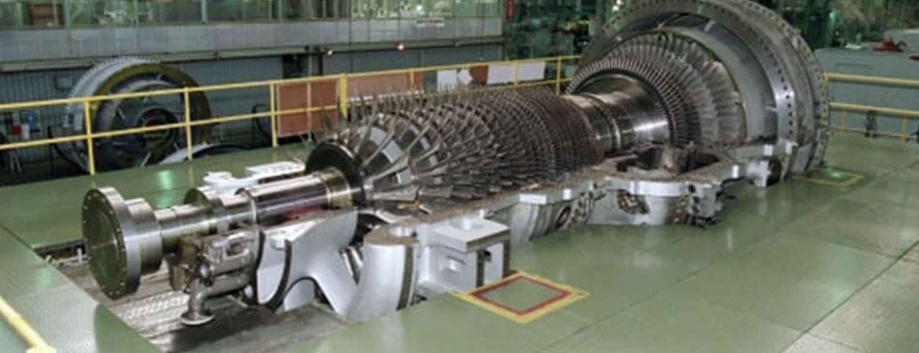
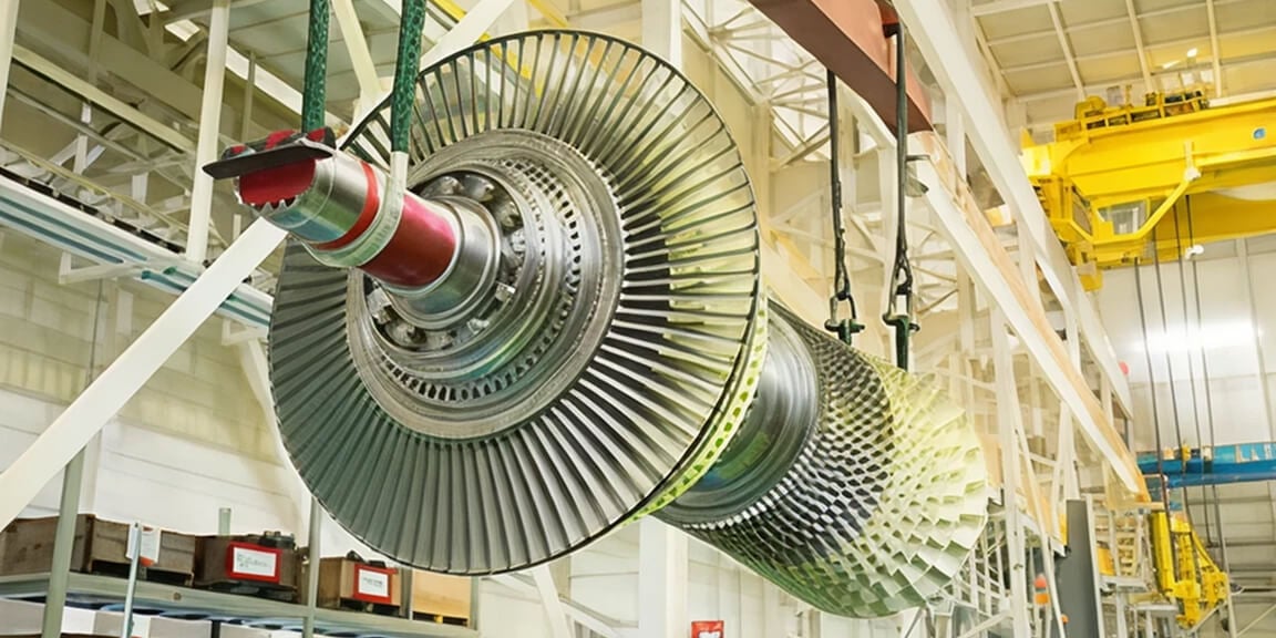
M701D Series
Large Capacity Gas Turbine - For 50Hz
Gas turbines for 50Hz power generation matched with diversification of fuels
Features
- Standalone Gas Turbine Output
- 140MW class
- Combined Cycle Output
- 210MW/430MW/650MW class
- Compatible with a wide range of fuels, including blast furnace gas (BFG).
- Proven design based on over 50 years of experience
Product Details
Configuration
| M701DA | ||
|---|---|---|
| Compressor | Number of Stages | 19 |
| Combustor | Number of Cans | 18 |
| Cooling Method | Air Cooled | |
| Turbine | Number of Stages | 4 |
| Rotor | Number of Rotors | 1 |
| Output Shaft | Cold End | |
| Rated Speed | 3,000 rpm | |
| Gas Turbine | Approx. L × W × H | 11.9 × 5.0 × 5.3 m |
| Approx. Weight | 240 ton | |
Simple Cycle Performance
| M701DA | ||
|---|---|---|
| Frequency | 50 Hz | |
| ISO Base Rating | 144.09 MW | |
| Efficiency | 34.8 %LHV | |
| LHV Heat Rate | 10,350 kJ/kWh | |
| 9,810 Btu/kWh | ||
| Exhaust Flow | 453 kg/s | |
| 999 lb/s | ||
| Exhaust Temperature | 542 °C | |
| 1,008 °F | ||
| Exhaust Emission | NOx | 25 ppm@15%O2 |
| CO | 30 ppm@15%O2 | |
| Turn Down Load | 75 % | |
| Ramp Rate | 9 MW/min | |
| Starting Time | 30 minutes | |
Combined Cycle Performance
| M701DA | ||
|---|---|---|
| 1 on 1 | Plant Output | 212.5 MW |
| Plant Efficiency | 51.4 %LHV | |
| 2 on 1 | Plant Output | 426.6 MW |
| Plant Efficiency | 51.6 %LHV | |
| Starting Time | 70 minutes | |
Performance Correction Curves
Effects of Compressor Inlet Temperature on Gas Turbine Performance (Typical)

Effects of Barometric Pressure on Gas Turbine Performance (Typical)

Typical Plant Layout - 1 on 1 configuration, single-shaft


- Gas Turbines
- Steam Turbines
- Generators
- Inlet Air Filter
- Heat Recovery Steam Generator (HRSG)
- Electrical / Control Package
- Main Transformer
- Condenser
Typical Plant Layout - 2 on 1 configuration


- Gas Turbines
- GT Generator
- Steam Turbines
- ST Generator
- Inlet Air Filter
- Heat Recovery Steam Generator (HRSG)
- Electrical / Control Package
- GT Main Transformer
- ST Main Transformer
- Condenser
Representative Example

Tohoku Electric Power Co., Inc.
| Country/Region | Japan |
|---|---|
| Plant | Higashi-Niigata Thermal Power Station Unit 3 |
| Plant specifications × Qty | Combined cycle×6 |
| Year of operation | 1984 started |

JFE Steel Corporation
| Country/Region | Japan |
|---|---|
| Plant | East Japan Works |
| Plant specifications × Qty | Combined cycle×1 |
| Year of operation | 1987 started |
Other Delivery Records
| Client / Plant | Country/Region | Year of starting operation | Plant specifications × Qty |
|---|---|---|---|
| The Hongkong Electric Co., Ltd. (HEC) / Lamma OCGT | Hong Kong | 2025 | Simple cycle × 3 |
| Turkmenenergo / Zerger Gas-Fired Power Plant | Turkmenistan | 2019 | Simple cycle × 3 |
| Shougang Jingtang United Iron & Steel Co., Ltd. / Caofeidian Plant | China | 2018 | Blast furnace gas-fired combined cycle × 1 |
Lifecycle & Operation Support Services
 Gas Turbines – ServicesComprehensive lifecycle services that support reliable gas turbine operation.
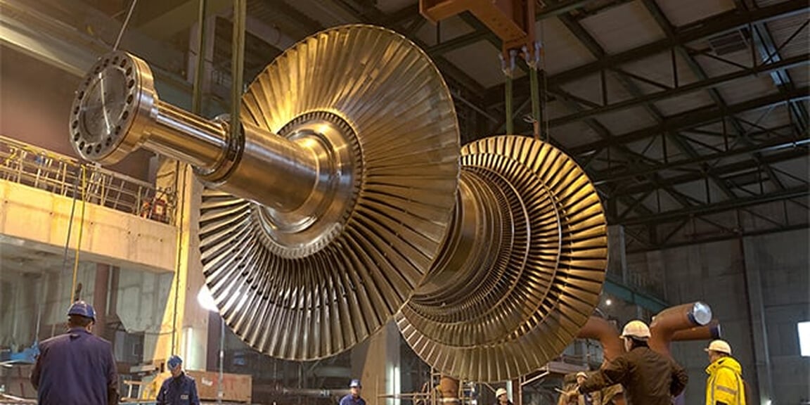 Long Term Service Agreement (LTSA)Predictable maintenance planning and long-term support to maintain stable plant performance.
 TOMONI® – Intelligent SolutionsDigital solutions that enhance plant performance, flexibility, and operational efficiency.
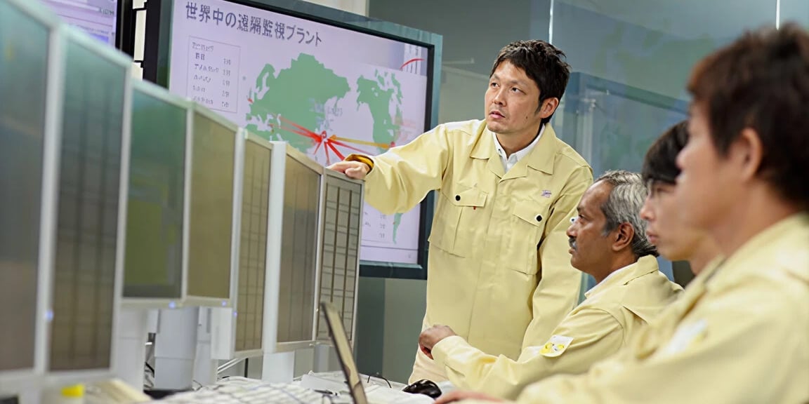 Support of Operation and MaintenanceWe comprehensively repair aging plants and aim to extend the life of facilities and equipment.
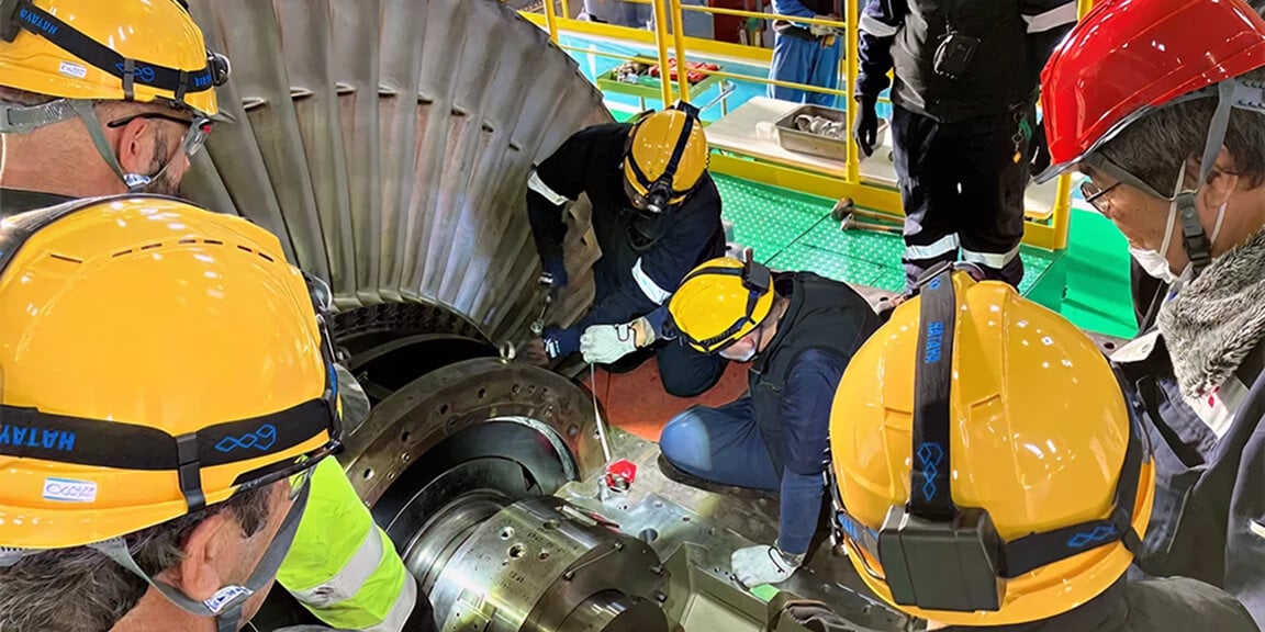 TrainingSkill-development programs for plant operators and maintenance engineers.
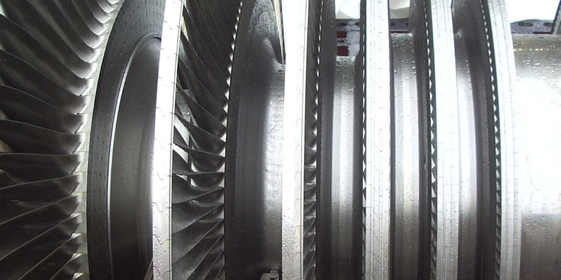 Steam Turbines – ServicesService solutions for steam turbines used in GTCC combined-cycle plants.
Insights
Explore industry insights related to clean power, decarbonization, and energy transition.
-
What are the most promising technologies for low-carbon hydrogen?
Power & Energy
-
AI in Manufacturing: Productivity, Protection and Maintaining a Human Touch
Power & Energy
-
Energy Explained: What is curtailment and how do we address it?
Power & Energy
-
Clean energy in APAC: balancing net zero, gas and nuclear
Power & Energy
-
From Niche to Necessity: Why CCUS is poised for breakout growth
Power & Energy