M701F Series

High-efficiency high-operability gas turbines for 50 Hz power generation incorporating J-Series technologies
Features
- Standalone Gas Turbine Output
- 380MW class
- Combined Cycle Output
- 570MW / 1,130MW class
- Combined Cycle Efficiency
- 62% or more
- Attaining High Performance and High Operability
- Application of J-Series technologies
- Unmatched reliability backed by a proven track record of over 24 million cumulative operating hours across the F-Series fleet
- Advanced thermal efficiency reaching over 62% in combined cycle through the integration of cutting-edge cooling and combustion technologies
Product Details
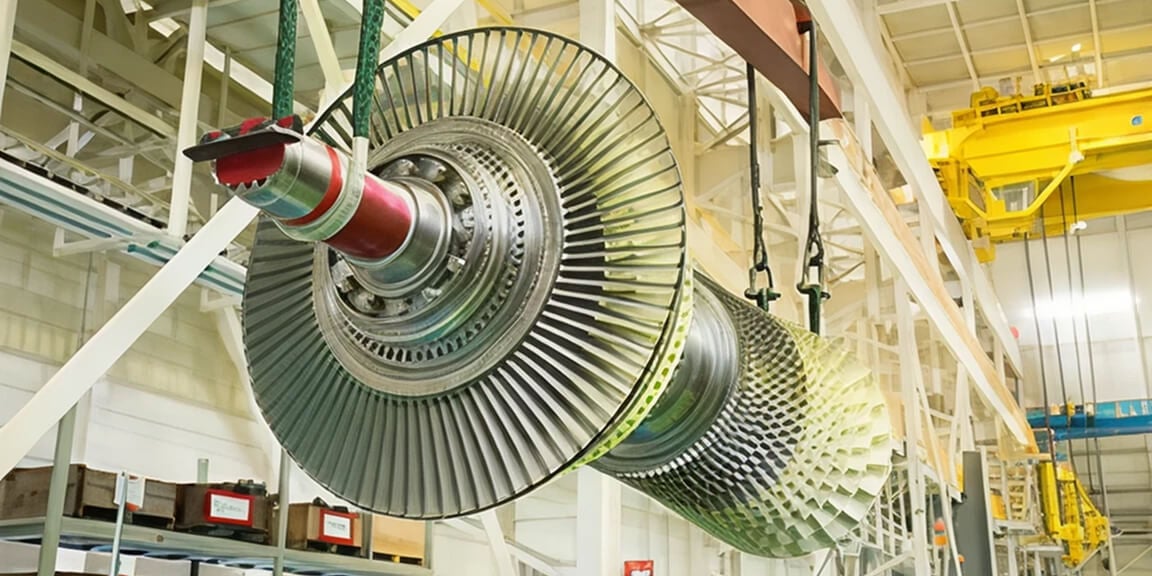
Overall Design
The gas turbine unit is based on the basic structure adopted in the early 1970s that has accumulated a track record of at least 50 years. Its main features are as follows:
- A compressor shaft end drive reduces the effect of thermal expansion on alignment
- A rotor with simple single-shaft two-bearing support
- A rotor structure has bolt-connected discs with the torque pins in the compressor section and CURVIC couplings in the turbine section to ensure stable torque transmission
- An axial flow exhaust structure advantageous in combined cycle plant layouts
- Horizontally split casings that facilitate field removal of the blades with the rotor in place

Key Component Technologies
Compressor
Variable inlet guide vanes ensure operational stability at the start-up and enhanced performance at partial load in combined cycle operation.
Combustor
A premixing low NOx combustor is composed of one pilot burner and eight main burners that surround it. The compressor has an air bypass mechanism that enables fuel-air ratio regulation in the combustion region.
Turbine
Rotating Blades at the first two stages are free-standing, while those at the third and fourth stages are integral shroud blades.
Stationary vanes are supported by blade rings that are independent at individual stages to prevent turbine casings from being affected by thermal expansion.
Explore more
Long-term Validation - T-POINT 2 Proving Ground for Gas Turbine Advancements
Mitsubishi Power has a unique design and validation approach, unlike any other Original Equipment Manufacturer (OEM). The current verification process for the J-series technology takes place at our grid-connected T-Point 2 commercial combined cycle power plant located at Takasago Machinery Works 1 km2 campus 48 km west of Kobe, Japan. In one single location, we house the four key pillars of validation: research and development, design, manufacturing, and full-scale validation. These turbine designs undergo long-term operation of at least 8,000 hours of validation, equivalent to nearly one year of normal operation.
Explore more
Hydrogen Capability
With Mitsubishi Power's hydrogen combustion technology, power plant owners can convert existing gas turbine combined cycle (GTCC) plants to hydrogen co-firing, reducing CO₂ emissions. In the future, it will also be possible to switch to 100% hydrogen combustion with minimal modifications.

Configuration
| M701F | ||
|---|---|---|
| Compressor | Number of Stages | 17 |
| Combustor | Number of Cans | 20 |
| Cooling Method | Air Cooled | |
| Turbine | Number of Stages | 4 |
| Rotor | Number of Rotors | 1 |
| Output Shaft | Cold End | |
| Rated Speed | 3,000 rpm | |
| Gas Turbine | Approx. L × W × H | 14.3 × 5.8 × 6.1 m |
| Approx. Weight | 415 ton | |
Simple Cycle Performance
| M701F | ||
|---|---|---|
| Frequency | 50 Hz | |
| ISO Base Rating | 385 MW | |
| Efficiency | 41.9 %LHV | |
| LHV Heat Rate | 8,592 kJ/kWh | |
| 8,144 Btu/kWh | ||
| Exhaust Flow | 748 kg/s | |
| 1,650 lb/s | ||
| Exhaust Temperature | 630 °C | |
| 1,167 °F | ||
| Exhaust Emission | NOx | 25 ppm @15%O2 |
| CO | 10 ppm @15%O2 | |
| Turn Down Load | 45 % | |
| Ramp Rate | 38 MW/min | |
| Starting Time | 30 minutes | |
Combined Cycle Performance
| M701F | ||
|---|---|---|
| 1 on 1 | Plant Output | 566 MW |
| Plant Efficiency | 62.0 %LHV | |
| 2 on 1 | Plant Output | 1,135 MW |
| Plant Efficiency | 62.2 %LHV | |
| Starting Time | 45 minutes | |
Performance Correction Curves
Effects of Compressor Inlet Temperature on Gas Turbine Performance (Typical)

Effects of Barometric Pressure on Gas Turbine Performance (Typical)

Typical Plant Layout - 1 on 1 configuration, single-shaft


- Gas Turbines
- Steam Turbines
- Generators
- Inlet Air Filter
- Heat Recovery Steam Generator (HRSG)
- Electrical / Control Package
- Main Transformer
- Condenser
Typical Plant Layout - 2 on 1 configuration


- Gas Turbines
- GT Generator
- Steam Turbines
- ST Generator
- Inlet Air Filter
- Heat Recovery Steam Generator (HRSG)
- Electrical / Control Package
- GT Main Transformer
- ST Main Transformer
- Condenser
Representative Example

Azer Enerji
| Country/Region | Azerbaijan |
|---|---|
| Plant | Shimar Power Plant |
| Plant specifications × Qty | Combined cycle ×2 |
| Year of operation | 2002 started |

Tohoku Electric Power Co., Inc.
| Country/Region | Japan |
|---|---|
| Plant | Sendai Thermal Power Station Unit 4 |
| Plant specifications × Qty | Combined cycle ×1 |
| Year of operation | 2010 started |

PT Perusahaan Listrik Negara(PLN)
| Country/Region | Indonesia |
|---|---|
| Plant | Muara Karang Power Plant |
| Plant specifications × Qty | Combined cycle × 2 |
| Year of operation | 2009 started |

Nuon N.V.
| Country/Region | Netherlands |
|---|---|
| Plant | Nuon Magnum Power Plant |
| Plant specifications × Qty | Combined cycle × 3 |
| Year of operation | 2013 started |
Other Delivery Records
| Client / Plant | Country/Region | Year of starting operation | Plant specifications × Qty |
|---|---|---|---|
| Snowy Hydro/ Hunter Power Plant | Australia | 2023 | Combined cycle × 2 |
| The Hongkong Electric Company (HEC) / Lamma Power Station-L12 | Hong Kong | 2023 | Combined cycle × 2 |
| The Hongkong Electric Company (HEC) / Lamma Power Station | Hong Kong | 2020 | Combined cycle × 1 |
| Sharjah Electricity and Water Authority (SEWA) / Layyah Combined Cycle Power Plant | UAE | 2022 | Combined cycle × 2 |
| Fukushima Gas Power Co., Ltd. / Fukushima Natural Gas Power Plant | Japan | 2020 | Combined cycle × 2 |
Related Case Studies / News
-
Mitsubishi Power Receives Gas and Steam Turbine Orders for 500MW Combined Cycle Power Plant in Sarawak, Malaysia
2024-08-05Press Release
-
Mitsubishi Power Receives Order from HK Electric for Natural-gas-fired GTCC Power Generation Equipment
2024-04-09Press Release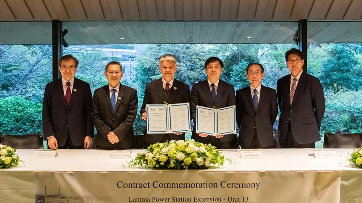
-
Mitsubishi Power to equip Singapore's Open Cycle Gas Turbine power station with state-of-the-art hydrogen-ready gas turbines
2023-05-19Press Release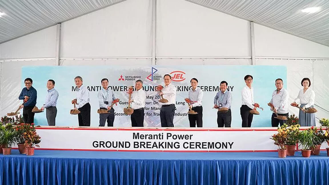
Lifecycle & Operation Support Services
 Gas Turbines – ServicesComprehensive lifecycle services that support reliable gas turbine operation.
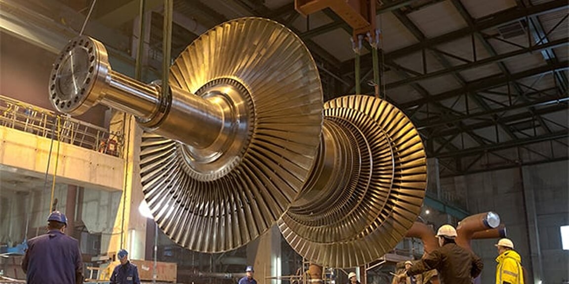 Long Term Service Agreement (LTSA)Predictable maintenance planning and long-term support to maintain stable plant performance.
 TOMONI® – Intelligent SolutionsDigital solutions that enhance plant performance, flexibility, and operational efficiency.
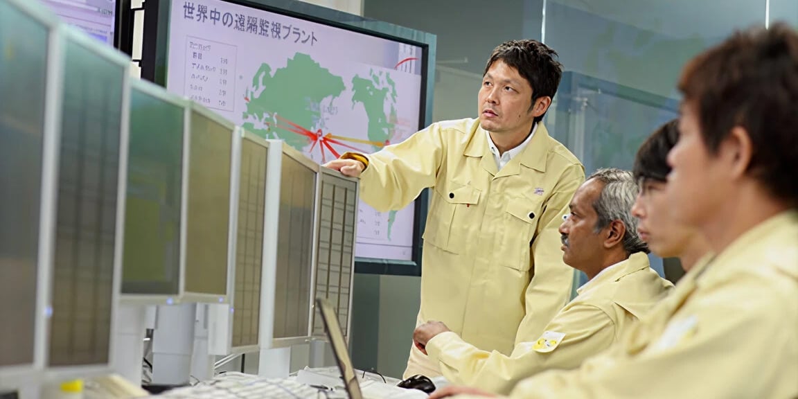 Support of Operation and MaintenanceWe comprehensively repair aging plants and aim to extend the life of facilities and equipment.
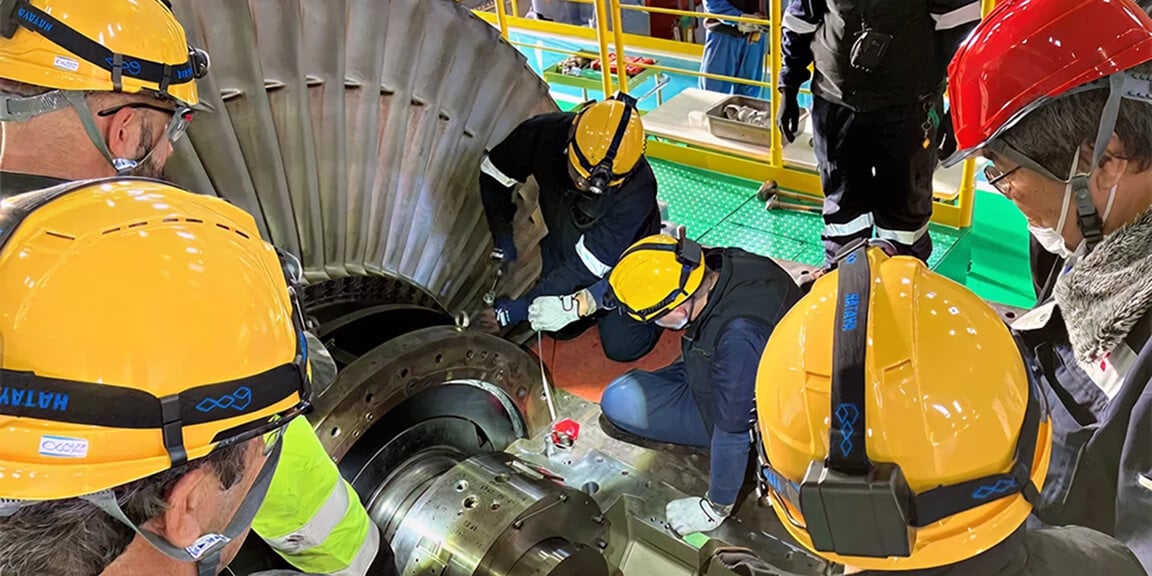 TrainingSkill-development programs for plant operators and maintenance engineers.
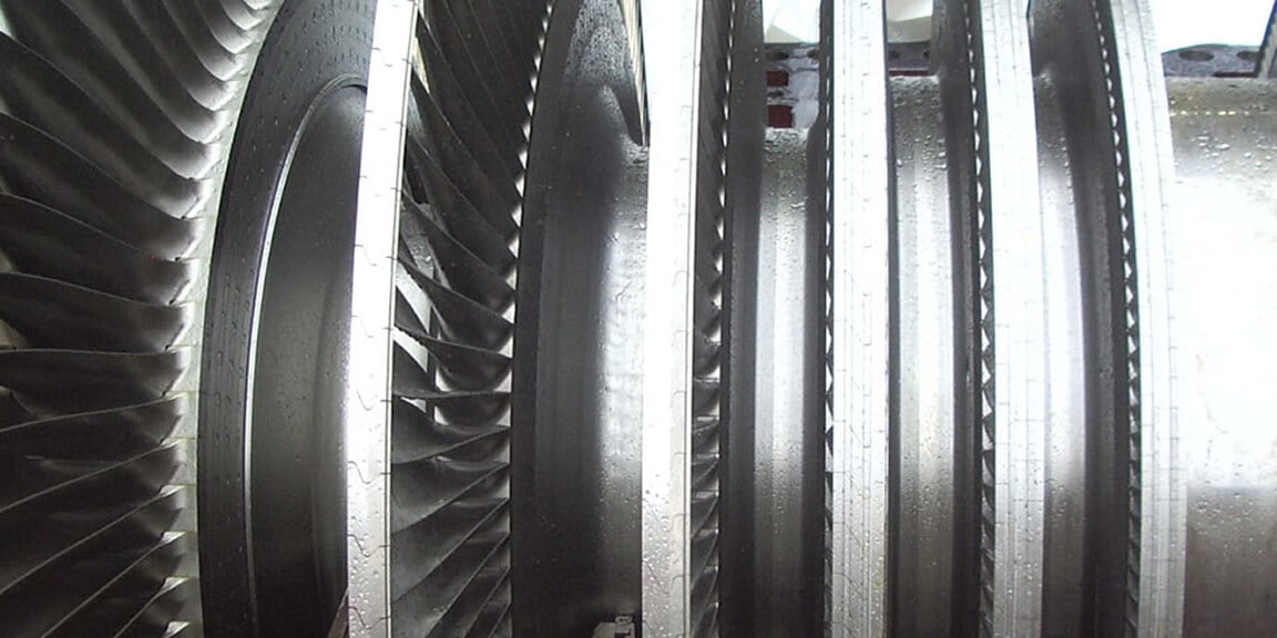 Steam Turbines – ServicesService solutions for steam turbines used in GTCC combined-cycle plants.
Insights
Explore industry insights related to clean power, decarbonization, and energy transition.
-
What are the most promising technologies for low-carbon hydrogen?
Power & Energy
-
AI in Manufacturing: Productivity, Protection and Maintaining a Human Touch
Power & Energy
-
Energy Explained: What is curtailment and how do we address it?
Power & Energy
-
Clean energy in APAC: balancing net zero, gas and nuclear
Power & Energy
-
From Niche to Necessity: Why CCUS is poised for breakout growth
Power & Energy