H-100 Series
-
Standalone Gas Turbine Output
100-120 MW class
-
Combined Cycle Output
150-170 MW / 300-350 MW class
-
Standalone Gas Turbine
Quick start-up in 10 minutes
-
Suited to power generation and mechanical drive applications
The world's largest-class high efficiency two-shaft gas turbines
The H-100 Series gas turbines were developed for utility customers and industrial customers in both 50 Hz and 60 Hz regions. The first unit came into commercial operation in 2010.
Then Mitsubishi Power continued its efforts to improve the design of the H-100 Series gas turbines. While incorporating advanced elemental technologies and material technologies verified with the H Series gas turbines, we are continuously working to improve performance.
H-100 Gas Turbines
Overview
H-100 Series units are the world's largest capacity two-shaft gas turbines based on a great deal of experience in manufacturing gas turbines and achievements in the development of the H-25 and H-15 Series.
They achieve high efficiency as part of combined cycle plants with heat recovery boilers, co-generation systems or other combined cycle power plants.
The H-100 Series features simple cycle gas turbine output of 105 MW to 116 MW and an output range of 150 MW to 350 MW in combined cycle. As two-shaft gas turbines, they are suited to mechanical drive applications.
Features
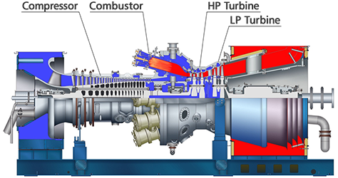
- Heavy duty design: A heavy and highly reliable structure designed in consideration of ease of maintenance and long-term continuous operation
- High efficiency: High performance in various power generation cycles (simple, combined and co-generation)
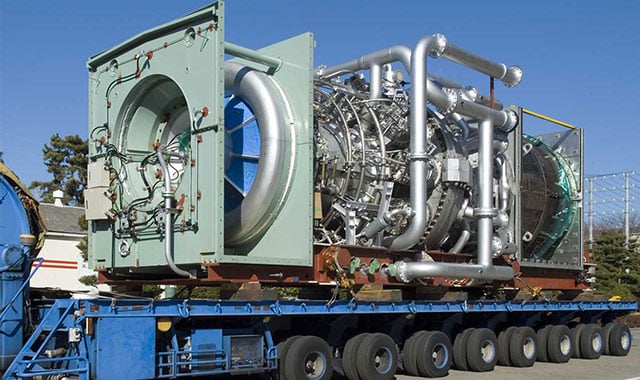
- Package type: Easy to carry and install
- The series is applicable not only for power generation but also for mechanical drive.
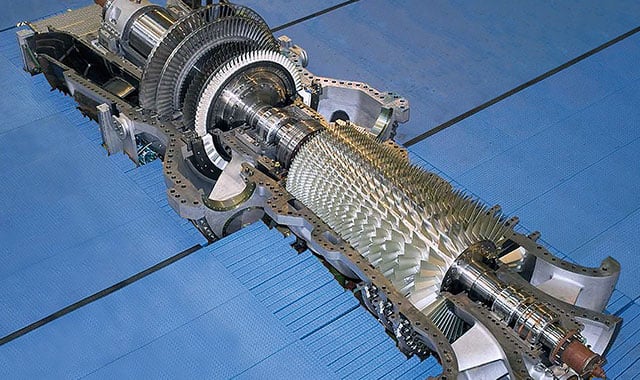
Configuration
| H-100 60Hz | H-100 50Hz | ||
|---|---|---|---|
| Compressor | Number of Stages | 17 | 17 |
| Combustor | Number of Cans | 10 | 10 |
| Cooling Method | Air Cooled | Air Cooled | |
| Turbine | Number of Stages | HP: 2 LP: 2 |
HP: 2 LP: 2 |
| Rotor | Number of Rotors | 2 | 2 |
| Output Shaft | Hot End | Hot End | |
| Rated Speed | HP: 4,580 rpm LP: 3,600 rpm |
HP: 4,580 rpm LP: 3,000 rpm |
|
| Gas Turbine | Approx. L × W × H | 12.1 × 4.5 × 5.4 m | 12.9 × 4.5 × 6.3 m |
| Approx. Weight | 175 ton | 216 ton | |
Simple Cycle Performance
| H-100 60Hz | H-100 50Hz | ||
|---|---|---|---|
| Cycle | 60 Hz | 50 Hz | |
| ISO Base Rating | 105.7 MW | 116.4 MW | |
| Efficiency | 38.2 % LHV | 38.3 % LHV | |
| LHV Heat Rate | 9,421 kJ/kWh | 9,400 kJ/kWh | |
| 8,930 Btu/kWh | 8,909 Btu/kWh | ||
| Exhaust Flow | 293 kg/s | 296 kg/s | |
| 646 lb/s | 652 lb/s | ||
| Exhaust Temp | 534 °C | 586 °C | |
| 993 °F | 1,087 °F | ||
| Emission | NOx | 9 ppm@15%O2 | 9 ppm@15%O2 |
| CO | 9 ppm@15%O2 | 9 ppm@15%O2 | |
| Turn Down Load | 50 % | 50 % | |
| Ramp Rate(Normal/Fast) | 8 MW/min / 26 MW/min | 9 MW/min / 29 MW/min | |
| Starting Time(Normal/Fast) | 22 minutes / 10 minutes | 22 minutes / 10 minutes | |
Combined Cycle Performance
| H-100 60Hz | H-100 50Hz | ||
|---|---|---|---|
| 1 on 1 | Plant Output | 150.0 MW | 171.0 MW |
| Plant Efficiency | 55.1 % LHV | 57.4 % LHV | |
| 2 on 1 | Plant Output | 305.7 MW | 346.0 MW |
| Plant Efficiency | 56.1 % LHV | 58.0 % LHV | |
| Starting Time | 45 minutes | 45 minutes | |
Mechanical Drive Performance
| H-100 - 3,600rpm | H-100 - 3,000rpm | |
|---|---|---|
| Output | 144,350 hp | 160,780 hp |
| 107.7 MW | 119.9 MW | |
| Efficiency | 38.9 % LHV | 38.9 % LHV |
| Heat Rate | 6,542 Btu/hp-hr | 6,549 Btu/hp-hr |
| 9,256 kJ/kWh | 9,266 kJ/kWh | |
| Exhaust Flow | 293 kg/s | 315 kg/s |
| 646 lb/s | 695 lb/s | |
| Exhaust Temp | 534 °C | 552 °C |
| 993 °F | 1,025 °F |
Performance Correction Curves
-
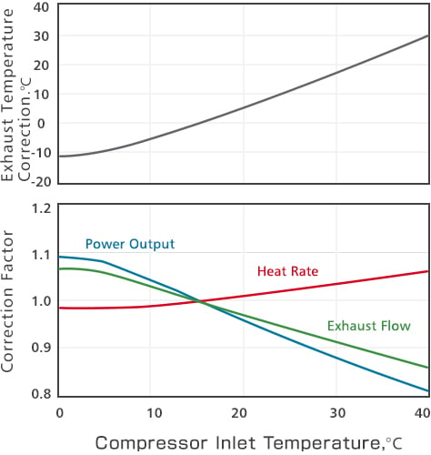
Effects of Compressor Inlet Temperature on Gas Turbine Performance (Typical)
-
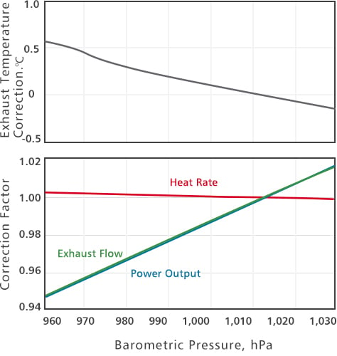
Effects of Barometric Pressure on Gas Turbine Performance (Typical)
Package Design
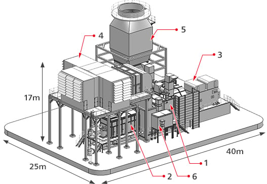
The package design of the H-100 Series has the following advantages.
- Minimize on-site installation work and time
- Flexible layout
- Short delivery period
Weight
| Package | H-100 | |
|---|---|---|
| 1 | Gas Turbine | 216 ton/50 Hz 175 ton/60 Hz |
| 2 | Lube Oil Tank, Starting Means and Auxiliaries | 89 ton |
| 3 | Generator | 152 ton |
| 4 | Air Intake System | 140 ton |
| 5 | Exhaust System | 139 ton |
| 6 | Gas Valve Compartment | 6 ton |
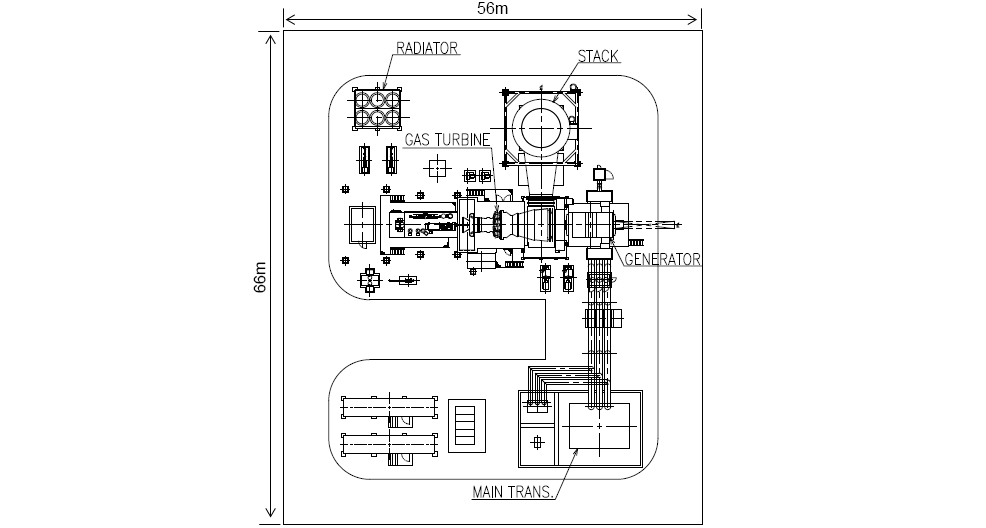
Typical Plant Layout: Simple Cycle

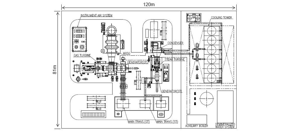
Typical Plant Layout: Co-generation
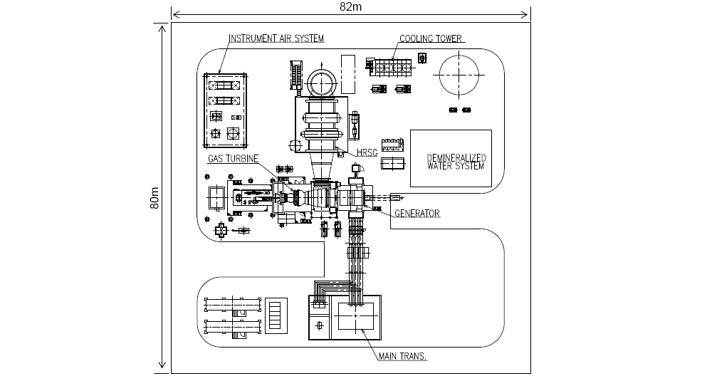

Typical Plant Layout: 1 on 1 Combined Cycle

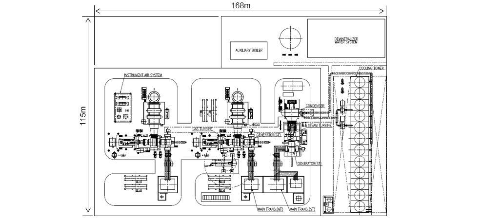
Typical Plant Layout: 2 on 1 Combined Cycle

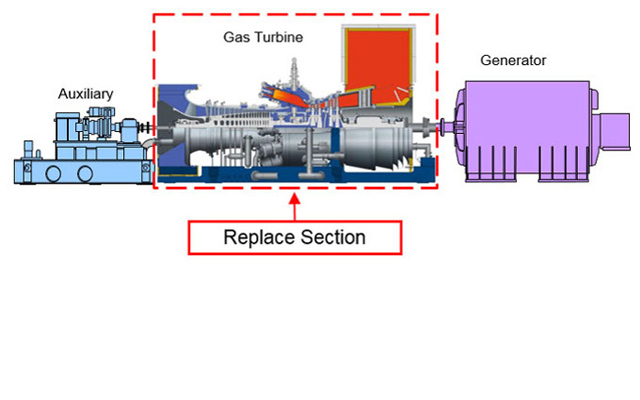
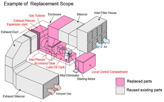
Replacing worn gas turbines with H-100 Series ones will result in reduced nitrogen oxide (NOx) and carbon dioxide (CO2) emissions as well as lower fuel consumption after improvement of plant efficiency.
Replacement of gas turbines paves the way for making the most of existing plant equipment and it is applicable not only for simple cycle plants but also for combined cycle plants.
Example of a Replacement of the Existing Combined Cycle System
Main Existing Equipment to be Reused
- Generators
- Heat Recovery Steam Generator (HRSG)
- Steam Turbines
- Electrical Equipment
Example of Evaluation of Performance Improvement by Replacement with H-100 Series Gas Turbines
| Item | Existing 1 on 1 Combined Cycle |
H-100 1 on 1 Combined Cycle | |
|---|---|---|---|
| 60 Hz | 50Hz | ||
| Output | Base | +13% | -3% |
| Efficiency | Base | +7% | +11% |
Delivery Records Example
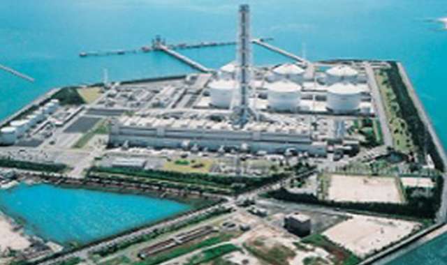
H-100 Series Gas Turbine Project (Japan)
Order Results Example
| Qty | Year of starting operation | Plant specifications | |
|---|---|---|---|
| Shin-Oita Power Station, Kyushu Electric Power Co., Inc. (Japan) | 6 | 2010~ | Combined cycle |
| Yanai Power Station, The Chugoku Electric Power Co., Inc. (Japan) | 6 | 2011~2015 | Combined cycle |
| Osaki CoolGen Corporation (Japan) | 1 | 2017 | Integrated Coal Gasification Combined Cycle (IGCC) Power Generation (Japan) |
| Futtsu Thermal Power Station, TEPCO Fuel & Power, Inc. (Japan) | 7 | 2016~2019 | Combined cycle |
| Torishima Energy Center, Gas and Power Co., Ltd. (Japan) | 1 | 2018 | Combined cycle |
Products
- GTCC
- Steam Power
- IGCC
- Geothermal
-
Gas Turbines
- Product Lineup
- Comparative Performance
-
Technical Information
- Gas Turbines for Mechanical Drive Applications
- Cutting-Edge Elemental Technology Producing 1600°C Class J Gas Turbines
- Development of High-Efficiency Gas Turbine Applying 1600°C Class J Technology
- Combustor Technologies Supporting Stable Operation
- Overview and Verification Status of T-Point 2 Demonstration Facility
- Comprehensive Efforts from Development to Manufacturing
- Summary of Orders
- Development History
- Product Selection Assistant (Middle & small Class)
- Aero-derivative Gas Turbines
- Steam Turbines
- Boilers
- Air Quality Control Systems (AQCS)
- Generators
-
Control Systems
- What is DIASYS?
- DIASYS Netmation
-
DIASYS Optional Products
- IR-S Infrared Flame Detector
- Net IR-S Infrared Flame Detector
- Rail Mounting Net IR-S
- Boiler Tube Leak Detector
- Shaft Vibration Analyzer
- Simulator
- Advanced Combustion Pressure Fluctuation Monitoring System (A-CPFM) / Combustion Pressure Fluctuation Monitoring System (CPFM)
- Multi-Coal Fired Boiler Optimum Control
- FXtoLS Adapter
- Fuel Cells
- Additive Manufacturing
- Catalogue
- HIACS Series
- Technical Report