Product Lineup
Gas Turbines
Mitsubishi Power has a wide range of gas turbines from the 30 MW class to the 570 MW class to meet diverse needs around the world.
Middle and Small Capacity Gas Turbines
(40 MW to 120 MW class)

Features
-
- Heavy duty models with high reliability
- Reliability of more than 99% (actual operating time of more than 13.7 million hours)
- Heavy duty models with high reliability
-
- Low environmental impact combustor compatible with a wide variety of fuels
- Natural gas, LPG, off gas, syngas, light oil, kerosene and bio-ethanol
- Low environmental impact combustor compatible with a wide variety of fuels
-
- High efficiency
- Overall efficiency of more than 80% at the combined heat and power (CHP) plant using exhaust gas from the gas turbine
- High efficiency
-
- An optimal combined plant meeting various power demands
- A lineup of models with an output range from 60 MW to 350 MW and a high plant efficiency of 55-58%
- An optimal combined plant meeting various power demands
-
- Support for flexible operation
- The investment can be recovered in several years.
- High load responsivity to support daily start and stop (DSS) operation
- Easy on-site maintenance
Lineup
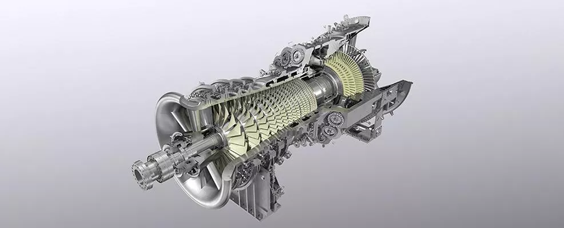
- H-25 Series (SC: 40 MW class, CC: 60 MW / 120 MW class)
- H-100 Series (SC: 100-120 MW class, CC: 150-170 MW / 300-350 MW class)
In-Depth Comparative Performance
Compare Mitsubishi Power gas turbines across output, efficiency, and technology generations.
Large Capacity Gas Turbines
(120 MW to 570 MW class)
Features
-
- Combined cycle plant performance with world-leading efficiency
- Plant efficiency of more than 64%
- Combined cycle plant performance with world-leading efficiency
-
- Low environmental impact combustor
- Mitsubishi Power Dry Low NOx combustor
- Low environmental impact combustor
-
- Applicable to combined heat and power plant
- High load responsivity to support daily start and stop (DSS) operation
Lineup For 50Hz
In-Depth Comparative Performance
Compare Mitsubishi Power gas turbines across output, efficiency, and technology generations.