Energy Management Systems
Overview
The energy management systems offered by DIASYS Netmation provide integrated monitoring of the various facilities and utilities used inside customer plants, and by visualizing the state of plant-wide energy usage, support customers' analysis work and operational improvements aimed at efficient energy operation.
Thanks to an extensive lineup of visualization tools, analysis and state monitoring can be implemented from various aspects.
Features
Reduced Energy Consumption with the Energy Visualization Function
By monitoring equipment energy usage and operational state in real-time, appropriate management of energy usage is implemented to achieve energy-saving operation of plants and equipment.
Coordination with Remote Monitoring Function
When the remote monitoring function and energy visualization function work together, appropriate management of energy usage can be carried out from a remote location.
Integration with Systems from Other Companies
As we can easily integrate with systems from other companies, different systems can co-exist without incurring special expenses.
System Configuration
Basic Configuration
Operator Station (OPS) | This equipment is used for monitoring and operation. This carries out monitoring and operation by displaying graphics and trends, showing alarms, and so on. |
Accessory Station (ACS) | This equipment is used for data collection. Manufacturing data collected from on-site manufacturing equipment is managed, and the data is output into forms. |
Engineering & Maintenance Station (EMS) | This equipment is used for maintenance. Maintenance tasks such as the creation and modification of logic and graphics screens, as well as system setup are performed. |
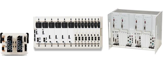
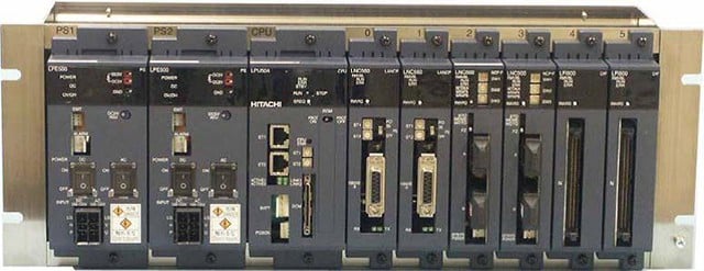
Compact Process Station (CPS) | Control equipment that performs I/O with instrumentation and other equipment installed on-site at the plant, as well as automated plant control and various computational processing. |
Features
Monitoring and Operational Features
Batch Monitoring
Multiple on-site manufacturing units controlled with programmable logic controllers (PLC) produced by other companies are monitored at once.
Based on the signals read from each PLC, plant operation can be centrally controlled, including the configuration of production plans and reflection in management information.
Electric Power Demand Monitoring
To prevent power consumption from exceeding contracted power, power consumption is measured according to a set cycle, producing an alarm when power consumption is predicted to exceed contracted power.
In addition, warning level notifications are issued as part of the demand control (peak cut control) feature. The amount of power to be adjusted as notified from the demand monitoring is used to derive the cut-off level, and pre-registered devices are controlled to avoid the excess power consumption.
Alarm Display
When an equipment malfunction occurs, a real-time alarm is displayed on the monitoring screen, supporting early discovery of abnormalities. A per-device history of alarm triggering and restoration can also be displayed.
The system includes an Automated Warning Message Function that displays warning names, trigger and restoration times line-by-line in chronological order on the monitoring screen, and an Error Warning List Screen that displays warning trigger and restoration information for each item chronologically. These functions facilitate analysis of the cause of an error.
Alarm Notification
Through an alarm notification feature that works over the Internet or PHS communications, even when an operator is away from the site, they can quickly take action to address an equipment fault.
Trend Display
Product manufacturing status, equipment operational status and fault signals can be managed through a trend display.
A per-lot trend function that displays trends from lot start to completion is also included.
Management Support Features
Form Features
With daily, weekly, monthly and annual reports, forms are managed in the format best suited to the customer.
In terms of data prepared for form output, by using snapshot CSV and trend CSV files, manufacturing data from lot start to completion and operational data can be summarized in lot forms.
A file listing the warnings generated on a monthly basis can also be created based on the event CSV file.
Production Planning Control
By setting variables such as product model, quantity and work type on a daily, weekly or monthly basis, systematic plant operation can be achieved.
Energy Consumption Rate Control
By applying logical computations to the signals collected from PLCs produced by other companies, specific energy consumption can be managed through graphics and trend displays.
Maintenance Records Display
On the maintenance screen of the engineering tool, device information, maintenance details and operating times for each device entered into the system is displayed on a per-device basis. In addition, when the designated maintenance cycle time for each device has elapsed, a warning can also be generated.
Weekly Timer Setting
By setting start-up times for each piece of on-site manufacturing equipment, wasted equipment operation is eliminated.
Optional Features
Energy Visualization Function
With a wide range of monitoring and analysis features including basic unit calculations and energy consumption, CO2 conversion and a comparison of equipment operating statuses with the use of Gantt charts, efficient plant operation and reduced energy consumption is achieved.
Remote Monitoring Function
The Internet-based remote monitoring function allows production status to be verified from a different building inside the plant.
Mitsubishi Power has also developed a communications protocol designed for remote monitoring. Using this protocol, screens can be displayed at the same speed as an on-site Operator Station (OPS), even over an analog telephone line.
Products
- GTCC
- Steam Power
- IGCC
- Geothermal
-
Gas Turbines
- Product Lineup
- Comparative Performance
-
Technical Information
- Gas Turbines for Mechanical Drive Applications
- Cutting-Edge Elemental Technology Producing 1600°C Class J Gas Turbines
- Development of High-Efficiency Gas Turbine Applying 1600°C Class J Technology
- Combustor Technologies Supporting Stable Operation
- Overview and Verification Status of T-Point 2 Demonstration Facility
- Comprehensive Efforts from Development to Manufacturing
- Summary of Orders
- Development History
- Product Selection Assistant (Middle & small Class)
- Aero-derivative Gas Turbines
- Steam Turbines
- Boilers
- Air Quality Control Systems (AQCS)
- Generators
-
Control Systems
- What is DIASYS?
- DIASYS Netmation
-
DIASYS Optional Products
- IR-S Infrared Flame Detector
- Net IR-S Infrared Flame Detector
- Rail Mounting Net IR-S
- Boiler Tube Leak Detector
- Shaft Vibration Analyzer
- Simulator
- Advanced Combustion Pressure Fluctuation Monitoring System (A-CPFM) / Combustion Pressure Fluctuation Monitoring System (CPFM)
- Multi-Coal Fired Boiler Optimum Control
- FXtoLS Adapter
- DIASYS Solutions
- Fuel Cells
- Others
- Catalogue
- HIACS Series
- Technical Report