Engineering & Maintenance Station (EMS)
Overview
The Engineering & Maintenance Station (EMS) is a device that performs maintenance on various DIASYS Netmation services.
The EMS includes the following functions.
- Control system configuration
- Creation and modification of control logic for the Multiple Process Station (MPS) and Dependable Process Station (DPS)
- Creation of graphics for rendering on an Operator Station (OPS)
- Configuration of OPS functions
- Drawing management
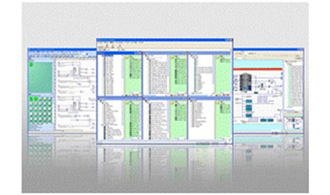
Engineering & Maintenance Station (EMS) Functions
Logic Creator - Control Logic Creation Tool
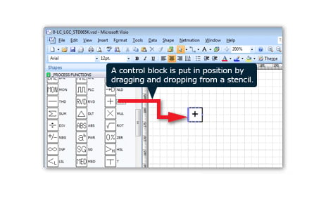
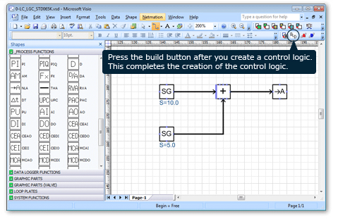
Logic Creator, a tool based on Microsoft Visio, is used to create control logic. Function block diagrams are used to describe control logic. Logic Creator allows users to easily create control logic without learning difficult operations by placing function blocks through drag-and-drop operation like Visio.
Extensive support functions for control logic creation including a script function for creating special function blocks and a macro function to register commonly-used logic are available.

Graphic Creator - Graphic Screen Creation Tool
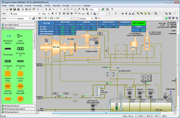
The graphic screens displayed on the OPS are created in Graphic Creator. Display areas can be independently customized, allowing the creation of aesthetically pleasing screens with attention to detail.
List Creator - Easily Edit Signals at Hundreds of Points at Once
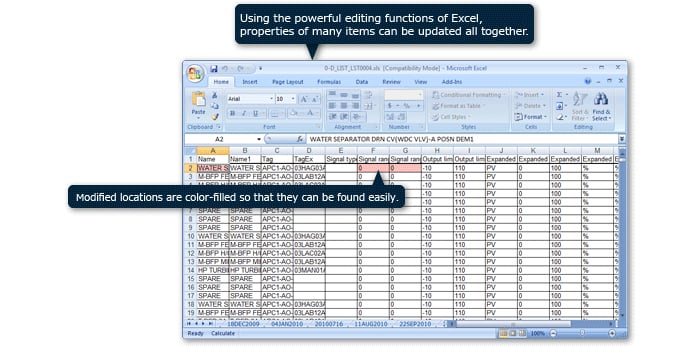
With List Creator, various signals, parameters and the properties of graphic components registered in the control logic can be edited at once in Excel.
Even when several hundred signals need to be updated, since changes can be reflected across the board by simply making changes from Excel instead of modifying each individual control logic, updating work can be carried out efficiently.
OPS Functions can be Configured Arbitrarily
With the EMS, the users can freely select whether to display alarm summaries, control loop plates or trend data on the OPS. This makes it possible to delete unneeded functions and develop OPS configurations with limited functions.
Simple Drawing Management
The control logic and graphic screens created for each function can be managed as drawings. As the drawings are automatically updated when changes are made to the underlying control logic or graphics, there is no risk of forgetting to reflect changes. Revision history and the ability to insert comments are also available. There is also a function to output to a PDF file.
Products
- GTCC
- Steam Power
- IGCC
- Geothermal
-
Gas Turbines
- Product Lineup
- Comparative Performance
-
Technical Information
- Gas Turbines for Mechanical Drive Applications
- Cutting-Edge Elemental Technology Producing 1600°C Class J Gas Turbines
- Development of High-Efficiency Gas Turbine Applying 1600°C Class J Technology
- Combustor Technologies Supporting Stable Operation
- Overview and Verification Status of T-Point 2 Demonstration Facility
- Comprehensive Efforts from Development to Manufacturing
- Summary of Orders
- Development History
- Product Selection Assistant (Middle & small Class)
- Aero-derivative Gas Turbines
- Steam Turbines
- Boilers
- Air Quality Control Systems (AQCS)
- Generators
-
Control Systems
- What is DIASYS?
- DIASYS Netmation
-
DIASYS Optional Products
- IR-S Infrared Flame Detector
- Net IR-S Infrared Flame Detector
- Rail Mounting Net IR-S
- Boiler Tube Leak Detector
- Shaft Vibration Analyzer
- Simulator
- Advanced Combustion Pressure Fluctuation Monitoring System (A-CPFM) / Combustion Pressure Fluctuation Monitoring System (CPFM)
- Multi-Coal Fired Boiler Optimum Control
- FXtoLS Adapter
- Fuel Cells
- Additive Manufacturing
- Catalogue
- HIACS Series
- Technical Report